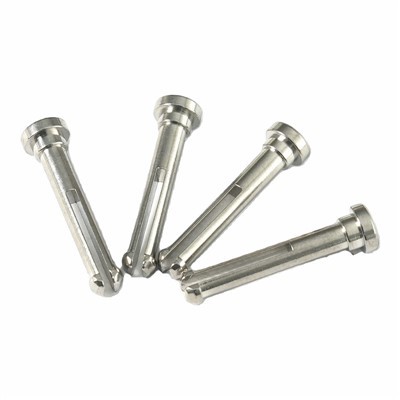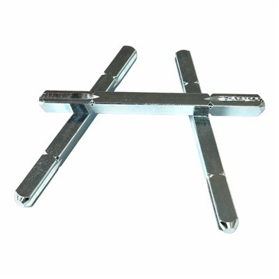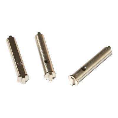

CNC Guide Bushings serve as critical alignment hardware, ensuring accurate axial positioning and controlled linear guidance between sliding pins, shafts, and mating die plates. Manufactured using high-precision multi-axis turning equipment, each sleeve is engineered to maintain tight bore concentricity, smooth internal surface finishes, and predictable clearance fits under repeated mechanical motion.
Core Operational Functions
Controlled Motion Guidance: Maintains strict axial alignment between sliding components, preventing mechanical binding and lateral deflection under heavy operational loads.
Friction and Wear Reduction: Precision-finished internal bores minimize surface friction, extending the service life of both the bushing and the mating shaft.
Exact Print Compliance: Custom outer profiles, shoulder geometry, and internal lubrication channels are produced precisely according to customer technical drawings.
Technical Specifications
|
Feature |
Machining Capability & Standard |
|
Bore Tolerance |
Down to ±0.005 mm – ±0.010 mm (IT6 to IT7 class) |
|
Outer Diameter Tolerance |
Down to ±0.010 mm – ±0.015 mm |
|
Surface Roughness |
Internal bore Ra 0.4 µm to Ra 0.8 µm |
|
Concentricity / Runout |
Within 0.005 mm to 0.010 mm TIR |
|
Hardness Range |
Up to HRC 58-62 (Heat treated steel options) |
|
Applicable Standards |
ISO 2768-m / Fine Machining Standards |
Industry Applications of CNC Guide Bushings
Injection Mold Base Tooling
Provides repeatable guidance for ejector plates and moving mold core components operating under high clamping pressures and elevated thermal cycles.
Metal Stamping and Press Dies
Ensures accurate punch-to-die alignment during high-speed, repetitive stamping operations where lateral drift causes premature tool wear.
Automation Jigs and Assembly Fixtures
Delivers precise locating reference points for robotic end-effectors, pneumatic actuators, and automated clamping mechanisms.
Reciprocating Mechanical Assemblies
Serves as replaceable wear sleeves inside industrial pumps, hydraulic guide blocks, and linear power transmission systems.
Material Selection Options
Carbon Steel (1045 / 4140):
Preferred for general structural tooling requiring high tensile strength and cost-effective machinability.
01
Tool Steel (D2 / SKD11 / O1):
Offers extreme wear resistance and high hardness following vacuum heat treatment for long-run stamping dies.
02
Stainless Steel (304 / 316 / 440C):
Selected for medical hardware, marine assemblies, and food processing machinery requiring corrosion resistance.
03
Copper Alloys & Brass (C36000 / SAE 660):
Provides excellent self-lubricating qualities, low friction coefficients, and superior thermal dissipation against steel pins.
04
Engineering Plastics (POM / PEEK):
Non-conductive, chemical-resistant material for lightweight electrical assemblies and cleanroom environments.
05
Custom Profile and Geometric Configurations
Straight Cylindrical Bushings: Standard straight outer diameter design suited for direct press-fit installation into counterbored housing pockets.
Flanged Guide Bushings: Features an integrated shoulder flange to absorb axial thrust loads and locate securely against mounting plates.
Stepped Outer Diameters: Designed with multiple external steps to align precisely with multi-tier housing bore configurations.
Secondary Machined Features: Internal oil retention grooves, cross-drilled lubrication ports, flat index flats, retaining ring slots, and entry chamfers added directly during turning cycles.
Critical Fit and Quality Control Protocols
Bore diameters are turned to match specified shaft dimensions for sliding, transition, or interference fit classes.
In-process dimensional checks using CMM, optical comparators, and air gauges verify critical internal diameters and runout parameters.
Bore surface finishes are verified via profilometer testing to ensure target roughness values are achieved prior to finishing operations.
Raw material certificates and heat-treatment reports are documented to guarantee mechanical properties match engineering callouts.
Technical Quotation Requirements
2D or 3D CAD Drawings: Provide drawings in PDF, STEP, or DWG format highlighting critical tolerances and baseline datum points.
Material and Hardness Callouts: Specify exact material grades, heat treatment requirements, or target surface hardness levels.
Mating Component Data: Indicate the exact diameter and tolerance of the mating guide pin to optimize internal bore clearance.
Post-Machining Treatments: List any required surface plating, anodizing, passivation, or custom packaging guidelines.
FAQ
Hot Tags: cnc guide bushings, China cnc guide bushings manufacturers, suppliers, factory, CNC Threaded Pipe Fittings